one step ahead


|
optimization
|
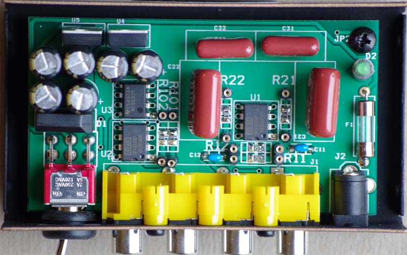
. Instructions for optimization of cartridge loading and preamplifier gain. NOTE: Before starting the process outlined below, unplug the power supply and allow 30 minutes for internal capacitors to discharge. Examples of optimum settings for various cartridges can be found here. 1. Remove the cover of the preamplifier by taking out two philips screws on the left and right side of the preamplifier:
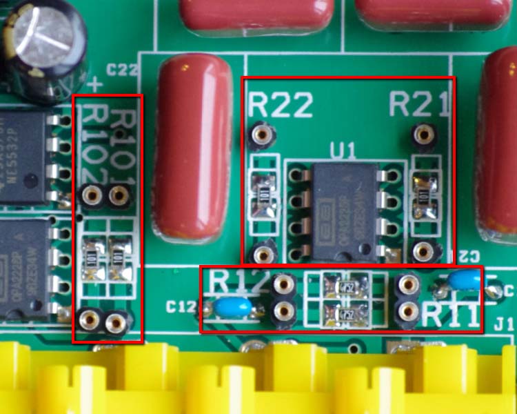
2. Identify sockets for load and sockets for resistors: resistors R11 and R12 set cartridge loading and R21, R22, R101 and R102 set the preamplifier gain.
3. Use the Load Settings Table to determine required load setting resistors (R11, R12) based on the cartridge specifications. NOTE: no resistors are required for 47 kohm load, however, we find that many cartridges with 47 kohm requirement actually perform better with 23 kohm load. As a general rule of thumb, load resistance 10 times the coil resistance offers the best results. We also provide 10 kohm loading option, which is rarely made available in competing products. This is particularly noticeable wihen the sound appears to be on the bright side. As a general rule, lower load resistance will result in lower noise operation and greater immunity to environmental effects (noise pickup, hum, etc.). 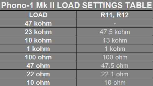 4.
Use the Gain Settings Table to determine required gain setting
resistors (R21, R22, R101 and R102) base on the cartridge requirements.
As a rule of thumb, MM cartridges will require 40dB of gain ,
High Output MC (HOMC) cartridges require 40-55dB of gain and Low
Output MC cartridges require 55-65dB. NOTE: Any combination of gain and
loading is possible. However, in order to maximize performance,
increase immunity to noise and hum and lower the noise, general rule is
to use minimum gain that still provides adequate output. 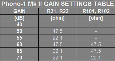 5.
All resistors needed to set any combination of load and gain are
included with the preamplifier. They come pre-cut and pre-formed, ready
for installation. 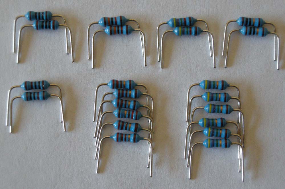 6. There is total of 22 resistors, 7 different values: - 2 pcs: 47.5 kohm - 2 pcs: 13 kohm - 2 pcs: 1 kohm - 2 pcs: 100 ohm - 2 pcs: 200 ohm - 6 pcs: 47.5 ohm - 6 pcs: 22.1 ohm - 2 pcs: 10 ohm 7. Resistor values are color coded as follows (first four rings define value, last one is always brown denoting 1% tolerance): 47.5 kohm: Yellow, Purple, Green, Red, Brown 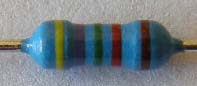 47.5 ohm: Yellow, Purple, Green, Gold, Brown 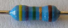 22.1 ohm: Red, Red, Brown, Gold, Brown 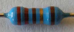 13 kohm: Brown, Orange, Black, Red, Brown 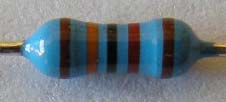 1 kohm: Brown, Black, Black, Brown, Brown 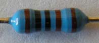 200 ohm: Red, Black, Black, Black, Brown 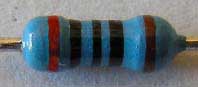 100 ohm: Brown, Black, Black, Black, Brown 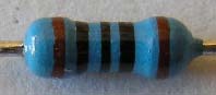 10 ohm: Brown, Black, Black, Gold, Brown 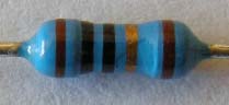 8. Identify the required values and
insert into the corresponding sockets. By using tweezers or nose pliers, resistor leads should be
firmly pushed into the sockets until they bottom out, after about 1/8"
(3mm). You will feel socket contacts scraping resistor leads, creating an air tight contact seal. The picture below shows the preamplifier board with all six resistors installed. Depending on a specific cartridge, there may be 0, 2, 4 or all 6 resistors required. The illustration below shows the example of optimized parameters for Denon DL-103 MC cartridge. 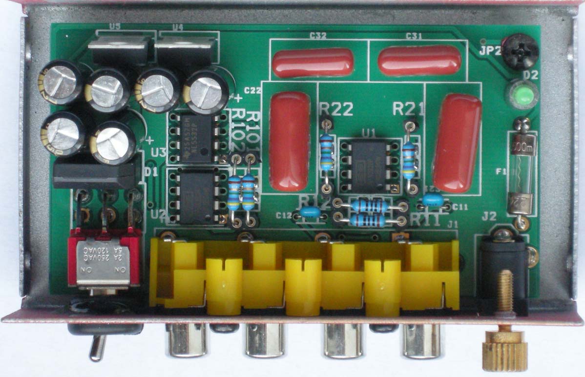 9. Once the required resistors are installed, the cover can be replaced and preamplifier is ready to use.
Vista Audio - a brand of Verty Technologies, Inc. |
|
|